You can find Camera Link scan examples for mE4VD4-CL/-PoCL platform in the following sections. In subsection ' Camera Link Area Scan Cameras ' examples for area scan cameras and in subsection 'Camera Link Line Scan Cameras' for line scan cameras are described.
The basic acquisition for area scan cameras is very easy. You simply need to select a suitable camera operator. Connect the camera operator to an ImageBuffer and DmaToPC operator. Any processing logic can be placed in between, preferably behind the buffer.
Simply connect the three operators and parameterize them to meet your requirements. If you are using a bit depth not equal to 8 or 16, you should consider a change of the output bit depth to one of these formats. In tutorial 'Applet Parameterization' explanations on bit depth modifications can be found.

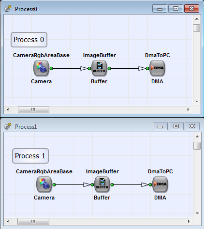
Figure 222. Basic Acquisition for Grayscale Camera Link Area Scan Cameras in Base Configuration Mode
The design includes two cameras in two different processes. You can find this example under \examples\Acquisition\BasicAcquisition\mE4VD4-CL\AreaScan\DualBaseAreaGray8.va. Check 'Multiple Processes' for more information on multiple processes. Under \examples\Acquisition\BasicAcquisition\mE4VD4-CL\AreaScan\BaseAreaGray8.va and \examples\Acquisition\BasicAcquisition\mE4VD4-CL\AreaScan\BaseAreaGray12.va you also have access to two basic single acquisition processes for 8 bit and 12 bit input bit depth.
The use of RGB cameras is similar to the use of grayscale cameras. Again, it might be necessary to modify the output bit depth. You can find the following example under \examples\Acquisition\BasicAcquisition\mE4VD4-CL\DualBaseAreaRGB24.va. It is an example with two processes analog to the example in 'Grayscale Camera Link Base Area'. An single process example for RGB area scan cameras is placed under \examples\Acquisition\BasicAcquisition\mE4VD4-CL\BaseAreaRGB24.va.
The use of medium cameras is similar to the use of cameras in Camera Link base configuration mode. The camera medium configuration camera operator allows a higher bandwidth.
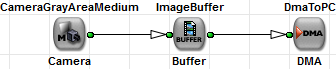
Figure 224. Basic Acquisition for Grayscale Camera Link Area Scan Cameras in Medium Configuration Mode
The examples for 8 bit and 12 bit input bit depth are placed under \examples\Acquisition\BasicAcquisition\mE4VD4-CL\AreaScan\MediumAreaGray8.va and \examples\Acquisition\BasicAcquisition\mE4VD4-CL\AreaScan\MediumAreaGray12.va.
Designs for RGB Camera Link cameras in medium configuration mode need a little modification compared to the other modes. For the medium configuration mode up to 85MPixel/s @ 36 bit per pixel i.e. 382.5MB/s can be transfered. The frame grabber RAM operators cannot process this high data rate. Thus, it is not possible to connect a single ImageBuffer operator to the camera module. From the operator documentation of operator ImageBuffer we know that only 64 bit can be connected to the buffer input. As we need parallelism 2 and 36 bit, we will get a DRC error. A simple solution to solve the bandwidth bottleneck is the use of two buffers in parallel. One buffer module will store the lower bits (LSBs) while another buffer module is used to store the upper bits (MSBs).
You can find this example under \examples\Acquisition\BasicAcquisition\mE4VD4-CL\AreaScan\MediumAreaRGB36.va.
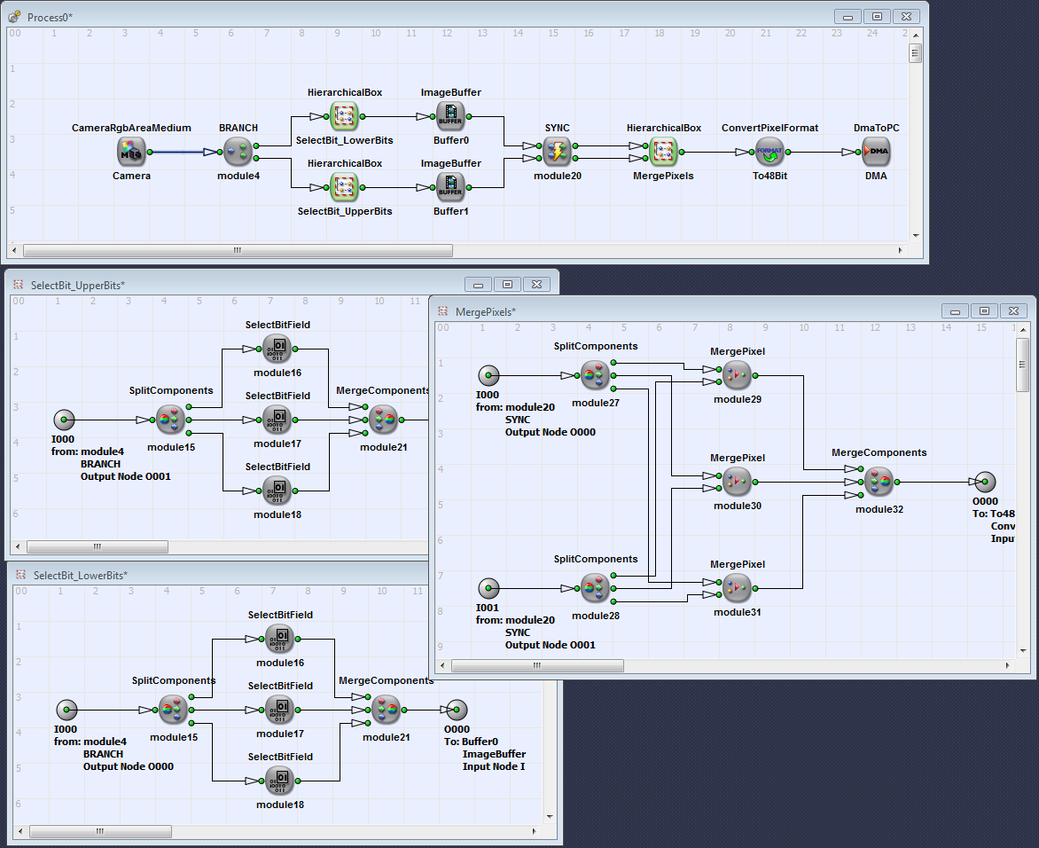
For the microEnable IV frame grabbers, designs for cameras in Camera Link full configuration mode need a little modification compared to cameras in medium or base configuration mode. The full configuration mode represents the fastest Camera Link mode. In theory, up to 850 Mbyte/s can be transfered. The frame grabber RAM operators cannot process this high data rate. Thus, it is not possible to connect a single ImageBuffer operator to the camera module. From the operator documentation of operator ImageBuffer we know that only 64 bit can be connected to the buffer input. We will obtain a DRC error when trying to build a design with only one ImageBuffer module. A simple solution to solve the bandwidth bottleneck is the use of two buffer operators in parallel. One buffer module will store the lower bits (LSBs), while another buffer module is used to store the upper bits (MSBs).
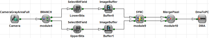
Figure 226. Basic Acquisition for Grayscale Camera Link Area Scan Cameras in Full Configuration Mode
The use of a 10 bit Camera Link full camera is similar. Change the properties in the camera module and link to 10 bit and parallelism 12. The SelectBitField modules now have to be changed to 5 bit and 5 bit offset. Note that the DMA output is 10 bit in this case. This is a packed format as one byte can contain multiple pixel. If you extend the output to 16 bit you might get a bandwidth limitation.
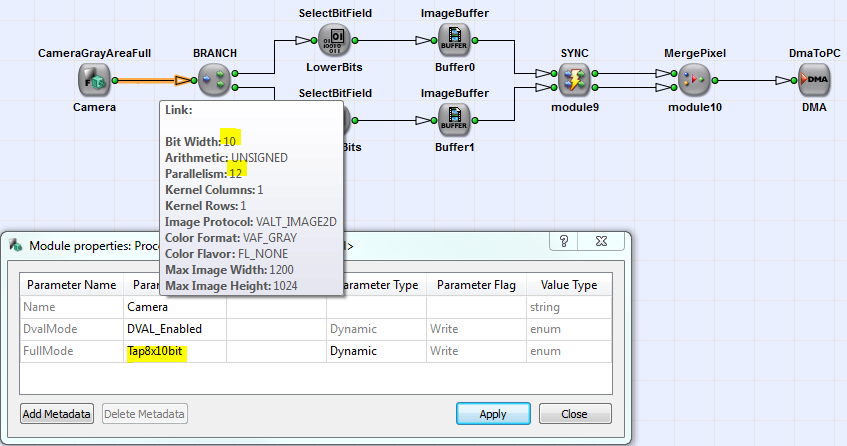
Figure 227. Basic Acquisition for Grayscale Camera Link Area Scan Cameras in Full Configuration 10 Bit Mode
You find the two basic acquisition examples for 8 bit and 10 bit input bit depth under \examples\Acquisition\BasicAcquisition\mE4VD4-CL\AreaScan\FullAreaGray8.va and \examples\Acquisition\BasicAcquisition\mE4VD4-CL\AreaScan\FullAreaGray10.va.
The acquisition for line scan cameras always requires the cut of the camera lines into images of a specific height. In detail, line scan cameras transfer line by line to the frame grabber. They will not include information on the end or start of a new image. The transfer of data from the frame grabber to the PC is required to be send in packages i.e. frames. Therefore, the lines from line scan cameras have to be assembled into an image of a specific height. There exist numerous possibilities to specify the height. One simple possibility is to accumulate a specific number of lines to form an image, or the image height is determined by other dynamic sources such as external image trigger gate signals. The following Camera Link examples are equipped with a TrgPortLine operator (see 'TrgPortLine'). This operator covers a wide range of trigger functionalities and can be used as an all-purpose trigger module. Besides the image trigger functionality it can be used to trigger the camera.For more information on the data transfer of line scan cameras 'Image Protocols, Image Dimensions and Data Structure' The following designs show simple Camera Link line scan VisualApplets implementations for basic acquisition.
The example (\examples\Acquisition\BasicAcquisition\mE4VD4-CL\LineScan\DualBaseLineGray8.va ) in the following figure is a dual process design for 8 bit input bit depth. The equivalent single process example is placed under \examples\Acquisition\BasicAcquisition\mE4VD4-CL\LineScan\BaseLineGray8.va.
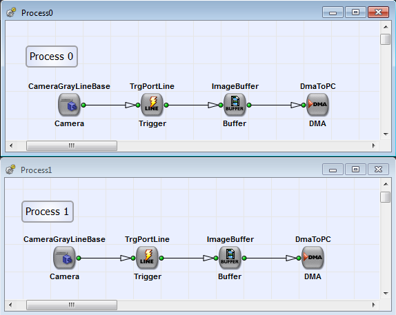
Figure 228. Basic Acquisition for Grayscale Camera Link Line Scan Cameras in Base Configuration Mode
The following dual process acquisition example for RGB cameras in Camera Link Base configuration mode is equivalent to the grayscale example in 'Grayscale Camera Link Base Line'. You can find it under \examples\Acquisition\BasicAcquisition\mE4VD4-CL\LineScan\DualBaseLineRGB24.va.
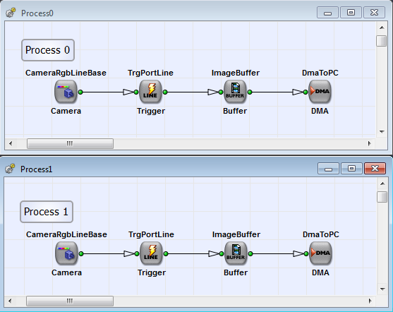
For the single process example see \examples\Acquisition\BasicAcquisition\mE4VD4-CL\LineScan\BaseLineRGB24.va.
The following two examples show acquisition designs for 8 bit (\examples\Acquisition\BasicAcquisition\mE4VD4-CL\LineScan\MediumLineGray8.va) and 12 bit (\examples\Acquisition\BasicAcquisition\mE4VD4-CL\LineScan\MediumLineGray12.va) input bit depth.
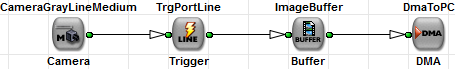
Figure 230. Basic Acquisition for Grayscale Camera Link Line Scan Cameras in Medium Configuration Mode
For medium 12 bit cameras two buffers are required as shown in the example for the area scan cameras (see 'RGB Camera Link Medium Area').
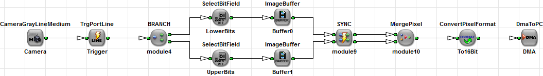
Figure 231. Basic Acquisition for Grayscale 12 Bit Camera Link Line Scan Cameras in Medium Configuration Mode
The example in the following figure presents an acquisition design in the Camera Link full configuration mode for 8 bit (\examples\Acquisition\BasicAcquisition\mE4VD4-CL\LineScan\FullLineGray8.va) and 10 bit (\examples\Acquisition\BasicAcquisition\mE4VD4-CL\LineScan\FullLineGray8.va) input bit width.
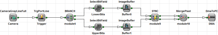
Figure 232. Basic Acquisition for Grayscale Camera Link Line Scan Cameras in Full Configuration Mode
